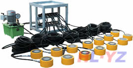
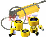
Double acting hydraulic cylind
发布时间:2009-09-20 来源:扬子工具集团 浏览次数:76616 When the combined seal is used,the amount of internal oil leakage shall be
limited up t0 2 times the value舒yen in Table l0.
In addition,when the piston ring is used,the amount shall be not more
than the value of Attached Fi9.1.
Table l0.Amount of internal oil leakage
Unit:ml,10 min
|
Bore oftube
mm
|
Amount of
oil leakage
|
Bore oftube
mm
|
Amount of
oil leakage
|
Bore oftube
mITI
|
Amount of
oil leakage
|
|
32(3i.5)
|
0.2
|
100
|
2.O
|
200
|
7.8
|
|
40
|
0.3
|
125
|
2.8
|
220(224)
|
10.O
|
|
50
|
0.5
|
140
|
3.0
|
250
|
11.0
|
|
63
|
0.8
|
160
|
5.0
|
|
|
|
80
|
1.3
|
180
|
6.3
|
||
5.5 Thrust efficiency When tested in accordance with l0.2.5,the value of
thrust efficiency of the cylinder shall be not less than 0.9.
Informative reference:The value of thrust efficiency varies depending on the
value of pressure,shape of packings,etc.
6. Construction
6.1 General con8truction
11
E 8354.1992
6.1.1—Construction—of cylinder Each part of the same type cylinders i aade by
the same manufacturer shall be interchangeable,and interchanging of t:1e parts
shall not cause remarkable change in their performances.The cylinder shall be
of such construction as to need no special tools at the time of disassemb.ing and
assembling for replacing or inspection of packings,gaskets and so on.
6.1.2一Fixing of rod and piston—The rod and piston shall be fixed secu:ely
together so as neither to loosen nor to allow the adjustment to get out 0’order
during the operation.When screw threads are used for fixing a rod and a pis七on,
the threads shall be in accordance with JIS B 0207,and the accuracy th 3reof
shall be of 6H/6 9 specified in JIS B 0211.
6.1.3—Mountin9—of switch The swish shall be fixed securely to the cy[inder so
as neither to be loosened nor to fall out of adjustment due to vibration.
6.1.4—Interception—of the air The cylinder shall be so constructed tha:the air
does not enter from the joint parts and seal parts.
6.1.5 Names of parts The names of parts of cylinders shall be in acc0:’dance
with Attached Fi9.3.
6.2一—Dust w—iper The gland of the rod cover shall provide a dust wipt肾to
prevent the rod packing from being damaged by external dust and the li【e.‘
6.2.2—P—o——r—t The ports shall be either the threaded joint type or pipe fie nge joint
type as specified in Table 31.
Screw threads of the screwed end of mating flanges shall be in acc ordance
with JIS B 0203,and those of welding end of mating flanges shall be of;SA
specified in JIS B 229 1,and there shall be no harmful defect in practice on the
mating face. .
To the pipe flange fittin9,a mating flange of screwed end or weldi:19 end
shall be attached.
For the gasket of the pipe flange fittin9,Class l gasket for static l tse speci—
fled in JIS B 2401 should preferably be used.
6.2.3 Cushioning The cylinder containing
should be so constructed as to be adjustable
the cushioning mechanism i:1 itself
by a needle valve and the li:【e.
6.2.4 Head cover。rod cover and piston The head cover,rod cover and piston
shall have robustness sufficient to withstand internal pressure,and the;,land
part(including bush)of rod cover and the piston shall slide smoothly anc【shall
not impair the mutual sliding surfaces even if subjected to the lateral l0;.d of the
rod.As an operating condition,the lateral load of the rod shall be about i/i00
the maximum cylinder force.
6.2.5 Cylinder tube The wall thickness of the cylinder tube,hereafter
refe-rred to as the”tube”,shall be not less than the value obtained from{he for-
mula below,and it shall have ample stiffness.
0:minimum value oftensile strength
(N/ram2){kgf/cm2}
When the tube is welded to the rod cover,head cover or the flange,the wall
thickness shall be made thicker,taking into consideration the effect of the weld.
in9.When the inside and outside of the pressure withstanding part of the tube is
machined(including working for steady rest)or threaded,the minimum wall
thickness shall be not less than t obtained as above.In this case,screw threads
shall generally conform to JIS B 0207.
6.2.6 Rod The rod diameter shall be selected on the basis of the buckling of
the rod and the piston speed,and it should be preforable that the rod is processed
with the width across flats for wrenchin9.The width across flat dimensions
should be as specified in JIS B l002.
The sliding part shall be processed with the electroplated coatings of chr0.
mlum tor engmeenng Purpose tor preventing tlaWS,nicks,rust,etc.
6.2.7.M.......o....u.....n.....t...i...n.....g.......p.....a....r....t..—s—The mounting parts shall be those of having sufficient
rigidity against reaction force due to operation,and furthermore shall meet the
following requirements: ‘ +
(1)The attaching face of the mounting part of the foot type cylinder shall be in
parallel with the centre line of the cylinder.
(2)The attaching face of the mounting part of the flange type cylinder shall be
at right angles to the centre line of the cylinder. 、
(3)The attaching face of the mounting part of the crevice type cylinder shall be
in parallel with the plane of swing of the cylinder,and the centre line of
hole shall pass through the centre line of the cylinder and be at right angles
to the plane of swin9.
(4)The attaching shaft of the mounting part of the trunnion type cylinder shall
be symmetrical with respect to the centre line of the cylinder,and shall be
at right angles to it.
6.2.8 Switch
that the piston
electric circuit
electric circuit
The switch shall be of a dip—proof type,and when it has sensed
is approachin9,an indicator light is lighted at the same time the
is closed,and when the piston has separated from the switch,the
is opened to put out the indicator light.
’I’ube bores and rod diameter8
rod diameters shall be as given
y.
劢e basic dimensions
in Table l l according to
13
B 8354.1992
of the tube)ores and
the series A,B,C,五
If it is difficult to follow the first choice of the dimensions due to st,eed.
buckling and the like,select the second choice.
Tolerances,circularities and cylindricities on the finished dimensi0『】IS of the
tube bores and the sliding portion of the rod shall conform to Table l2 fl ad Table
13 with respect to the basic dimensions.
Table l l.Basic dimensions of tube bores and rod diameters
|
|
1st choice
|
2nd choice
|
|||
|
Tube bore
|
Rod bore symbols
|
||||
|
A
|
B
|
C
|
X
|
|
|
|
32(31.5)
|
22(22.4)
|
18
|
14
|
20
|
|
|
40
|
28
|
22(22.4)
|
18
|
25
|
|
|
50
|
36(35.5)
|
28
|
22 (22.4)
|
32 (31.5)
|
|
|
63
|
45
|
36(35.5)
|
28
|
40
|
|
|
80
|
56
|
45
|
36 (35.5)
|
50
|
|
|
100
|
70 (71)
|
56
|
45
|
63
|
|
|
125
|
90
|
70(71)
|
56
|
80
|
t
|
|
140
|
100
|
80
|
63
|
90
|
|
|
160
|
110 (112)
|
90
|
70 (71)
|
100
|
{
|
|
180
|
125
|
100
|
80
|
110(112)
|
l
‘
|
|
200
|
140
|
Ii0(112)
|
90
|
125
|
1I
|
|
220(224)
|
160
|
125
|
100
|
140
|
1:
|
|
250
|
180
|
140
|
110 (112)
|
160
|
1:
|
Remarks l.Numerical values given in parentheses should not be used,as faj as pos-
sible.
Combination of a tube bore and a rod diameter shall be selected{Lccording
to nominal pressure,length of stroke and rod material.
The values of piston-rod diameter and bore diameter which are n 3t in
accordance with this Table shall be selected from JIS B 8366.
14
B 8354.1992
Table l2.Finished dimenmons of tube bores
Unit:mm
|
|
When piston ring is used
|
When packing other than
Plston nng is used
|
|||
|
。I、lbe bore
|
TOlerance on
finished
dimension
|
Circularity
|
Cyhndricity
|
Tolerance on
finished
dimension
|
Circularity
and
cylindricity
|
|
32 40 50
|
+0.025
0
|
0.019
|
0.025
|
+0.062
0
|
0.062
|
|
63 80
|
+0.030
0 .
|
0.Ol9
|
0.030
|
+0.074
O
|
0.074
|
|
100
|
+0.035
0
|
0.022
|
0.035
|
+0.087
O
|
0.087
|
|
125 140 160 180
|
+0.040
O
|
0.025
|
0.O40
|
+0.100
0
|
0.100
|
|
200 220 250
|
+0.046
O
|
0.029
|
0.046
|
+0.115
0
|
0.115
|
本文链接: http://www.yzgj.cn/yzgjcn_172.html
如需转载请注明:扬子工具液压千斤顶http://www.yzgj.cn
本文章总10页 上一页 1 2 3 4 5 6 7 8 9 10 下一页
上一篇:伸缩式套筒液压缸下一编:液压接头和插头尺寸规范
| 千斤顶相关知识 |
| ■液压千斤顶原理、发明、简介、工作原理图 ■液压专业英语词汇 ■液压系统的故障诊断常用方法 ■双作用单活塞杆液压缸 ■钻杆动力钳使用说明书 ■液压基础知识 |
| 液压千斤顶相关产品(请点击产品名称查看详细资料) |
|
|
大吨位分离式液 压顶 |
|
|
空间窄小-如桥梁 更换支座 |
|
|
具有拉伸功能空 心液压顶 |
|
|
需长时间支撑重 物液压顶 |
|
|
小吨位分离式液 压顶 |
|
|
大吨位液压顶旧 型号 |
|
|
|
| 液压千斤顶选型调查表(在括号中填上数据,并留下联系方法,最后再提交) |


