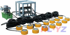
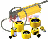
Double acting hydraulic cylind
发布时间:2009-09-20 来源:扬子工具集团 浏览次数:7662230
B 8354.1992
Table 29.Intermediate fixed trunnion type cylinders(Type TC)
for 7 MPa{70 kgf/cm2)and l4 MPa{140 kgf/cm2)
UIlit:mm
|
Tubebore
|
刃玎
|
弛
|
知
|
足
|
X1 1
|
||||
|
32(31.5)
|
58
|
O
一0.3
|
20
|
±0.3
|
20
|
一O.O40
一0.092
|
2
|
113+1 Stroke
|
300 and under
±1.25
|
|
40
|
69
|
20
|
20
|
2
|
113++Stroke
|
Over300 upto
|
|||
|
50
|
85
|
0
—0.35
|
25
|
25
|
2.5
|
121+1 Stroke
|
and ind.1000
±1.6
|
||
|
53
|
98
|
31.5
|
31.5
|
—0.050
|
2.5
|
132++Stroke
|
OverlooO
|
||
|
80
|
118
|
31.5
|
31.5
|
一O.112
|
2.5
|
145+-;Stroke
|
±2.0
|
||
|
loo
|
145
|
0
|
40
|
40
|
3
|
156++Stroke
|
|||
|
125
|
175
|
—0.4
|
50
|
50
|
3
|
177++Stroke
|
|||
|
140
|
195
|
O
一0.46
|
53
|
53
|
一O.060
—0.134
|
4
|
188++Stroke
|
||
|
160
●
|
218
|
71
|
±0.5
|
71
|
4
|
207+÷stroke
|
|||
|
180
|
243
|
80
|
80
|
4
|
216+1 Stroke
|
||||
|
200
|
272
|
0
|
90
|
90
|
—0.072
|
5
|
232+吉≯撇e
|
||
|
220(224)
|
300
|
一O.52
|
100
|
100
|
—0.159
|
5
|
241+2 Stroke
|
||
|
250
|
335
|
O
一0.57
|
100
|
100
|
5
|
271+1 Stroke
|
|||
Remarks:The letter symbol XI indicates the dimension in a state of the piston being
attheheadend.
Table 30.Intermediate fixed trunnion type cylinder(Type TC)
for 21 MVa{210 kgf/cm2)
|
广
‘-1
|
芝土』|
|
|
|
|
|
iL二』j
|
|
|
仆-一I·
|
l I
|
r。
|
、
|
||||
|
鬯
|
|
|
k.
|
/
|
|
|
|
|
一 Xl 。
|
|
||||||
31
t;8354.1992
|
Tube bore
|
到M
|
仡
|
7D
|
R
|
XI
|
||||
|
40
|
73
|
O
—O.3
|
25
|
±0.3
|
25
|
一O.040
—0.092
|
2.5
|
122+1 Sbroke
|
30
|
|
50
|
88
|
O
—O.3S
|
25
|
25
|
2.5
|
131+1 Stroke
|
m
arJ
|
||
|
53
|
106
|
31.5
|
31.5
|
一O.050
|
2.5
|
1鸫+丢s打oke
|
|||
|
80
|
128
|
O
—O.4
|
40
|
40
|
一O.112
|
3
|
169+1 Stroke
|
0、
|
|
|
100
|
170
|
50
|
50
|
3
|
181+1 Stroke
|
||||
|
125
|
205
|
O
—O.45
|
63
|
53
|
一O.060
一O.134
|
4
_
|
20s+{-Stroke
|
||
|
140
|
225
|
71
|
±0.5
|
71
|
4
|
218+1 Stroke
|
|||
|
160
|
255
|
O
—O.s2
|
80
|
80
|
4
|
242+1 Stroke
|
|||
Unit:mm
l andunder
土1.25
8r300 upto
lincl.1000
土1.6
8r1000
土2.0
Remarks:The letter symbolⅪindicates the dimension in a state of the P.ston being
at the head end.
7.10—Por—ts The ports shall be provided on the arbitrary side surface(f the
cylinder,and the sizes thereof shall conform to Table 3 1.
The symbols expressing the locations of the ports,as given in Fi9.;,shall be
as④,⑧,◎and◎in clockwise direction seen from the rod end.
32
B 8354.1992
|
Tube bore
|
Sizes of ports
|
|
|
mm
|
Designation of
screw fitting
|
Designation of
flange fitting
|
|
(31.5),32,40
|
Rc 3/8
|
(10)
|
|
50, 63
|
Rc拢
|
15
|
|
80, 100
|
Rc 3/4
|
20
|
|
125, 140, 160
|
Rc l
|
25
|
|
180
|
(Rc以)
|
32
|
|
200, 220,(224)
|
(Rc l拢)
|
40
|
|
250 +
|
(Rc 2)
|
50
|
Remarks l.Screw threads ofthe screw fittings shall be in actor-
dance with the taper pipe threads specifieds in JIS B
0203.
2. Sizes ofthe tube flanges other than馅a亡indicated in
parentheses shall be in accordance with JIS B 2291.
3. Numerical values of the tube bore and the designa.
tion of screw fittings given in parentheses should not
be used as far as possible.
Fi9.5.Symbols for indicating port position
◎
⑧
Foot type RectAn__gular flange type
④ @
⑥廖◎ ⑧母◎
⑥ ◎
Trunnlon type
,/
The appearance of each parts shall be as follows:
33
E 8354.1992
Castings hall be smooth both on inside and outside surfaces,and b≥free
from defects such as harmful blowholes,uneven thickness,and craf.ks.
Penetration in the weld zone shall be satisfactory,and be free frorr cracks,
adhesion of slag and the like.
Machined surfaces of the mounting part and others shall be treated against
rust with oil,coating material or by other appropriate means.
The tube shall be free from any harmful flaws,cracks,etc.,both On inside
and outside surfaces.
(5)The rod and the screw threads of its end shall be free from flaws,C racks,
and their surfaces shall be treated against rust with oil,coating m£terial or
by other appropriate means.
(6) Exterior of the cylinder shall be finish—coated after rust-preventive;reat—
ment.
The cylinder ports shall be covered to guard against dust with caps or the
like.
9. Materials The materials
those given in Table 32,or those
materials.
used for principal parts of cylinders sha II be
equivalent to or better in quality than hose
Table 32.Materials for principal parts used for cylinders
|
Names of parts
|
Matedal standards
|
|
Tube
|
J1SG3445
J1SG3446
JISG3473
|
|
Rod
|
JISG4051
|
|
Piston
|
J1SG3101
J1SG3201
J1S G 4051
J1S G 5501
|
|
Bush
|
FC 20 0fJIS G 5501
。ⅡS H 5111
|
|
Packin9,gasket
|
Materials given in
Table5
|
Remarks:‰n the working fluid other
than mineral working oil is used,
it should be preferable to select
the packing material in accor-
dance with”Informative Refer.
ence:Selection and usage of
packings and working fluid for
hydraulic cylders”.
本文链接: http://www.yzgj.cn/yzgjcn_172.html
如需转载请注明:扬子工具液压千斤顶http://www.yzgj.cn
本文章总10页 上一页 1 2 3 4 5 6 7 8 9 10 下一页
上一篇:伸缩式套筒液压缸下一编:液压接头和插头尺寸规范
| 千斤顶相关知识 |
| ■液压泵工作原理 ■液压千斤顶定义,液压执行元件(马达)的术语 ■液压千斤顶及胶管的清洁度指标 ■液压千斤顶高压胶管、高压硬管外径参考 ■螺纹扣型的种类和特点 ■钢材基础知识 |
| 液压千斤顶相关产品(请点击产品名称查看详细资料) |
|
|
大吨位分离式液 压顶 |
|
|
空间窄小-如桥梁 更换支座 |
|
|
具有拉伸功能空 心液压顶 |
|
|
需长时间支撑重 物液压顶 |
|
|
小吨位分离式液 压顶 |
|
|
大吨位液压顶旧 型号 |
|
|
|
| 液压千斤顶选型调查表(在括号中填上数据,并留下联系方法,最后再提交) |


